
Since so many typical industrial automation sensors operate at 24 Vdc, it is important to understand two of the main variations of these solid-state devices.
Automation systems rely on discrete I/O signals, such as inputs from sensors and outputs to field devices. In some industries, these signals are operated at 120 Vac. A safer and more common option is to use 24 Vdc, and many end users choose devices with plug-and-cord connectors for easy installation and servicing. As it turns out, a little planning is necessary to ensure 24 Vdc sensors and PLC discrete input (DI) modules are connected properly.
The two types of 24 Vdc sensors are called PNP and NPN. These must be correctly matched with sinking and sourcing DI modules in order to function. It isn’t difficult, and in fact there is somewhat of a standard or at least a typical approach, as explained below.
 Transistor Effects
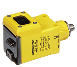
Solid-state electronics for discrete on/off sensor applications incorporate transistors, which are semiconductor devices configured to operate as tiny relays. They amplify a very small signal, such as the position sensing portion of a proximity switch, to turn a larger signal on or off. This larger signal can go to a DI point or an indicating light, or to any other device with an acceptable current rating. Transistors come in two types: PNP, or sourcing, and NPN, or sinking.
For PNP and NPN transistors, “P” and “N” refer to the arrangement of semiconductor materials. Transistors have connections termed as the base, collector and emitter. Fortunately, for industrial automation purposes, it really isn’t necessary to understand semiconductor physics.
PNP versus NPN Switching
Solid-state devices are active as opposed to passive, and therefore usually require some small amount of operating power. They are typically designed as three-wire devices with leads or connections for:
- +24 Vdc
- 0 Vdc
- Switched or sensor signal
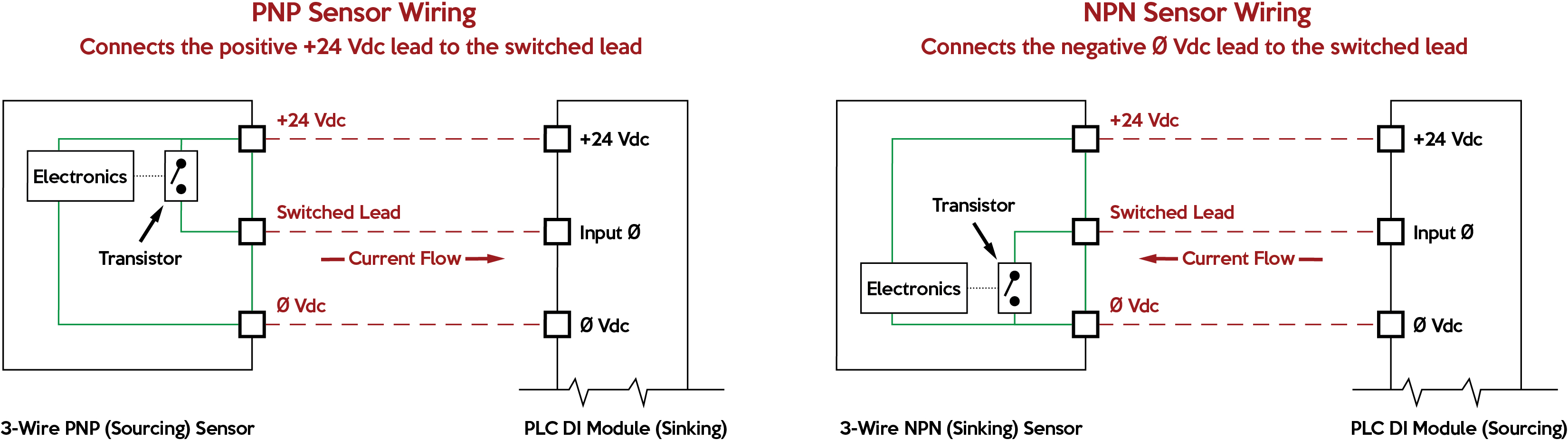
The +24 Vdc and 0 Vdc wires power the device. PNP or NPN style defines how the sensor operates the switched lead. Here are the two basic things to remember about PNP versus NPN field sensor operation when there is an “on” signal:
Three-Wire Devices and Leakage Current
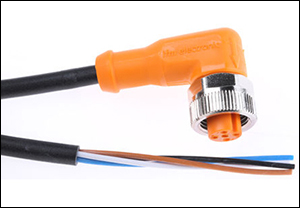
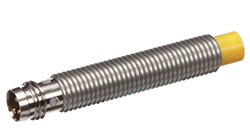
Many of these three-wire sensors use standard M12 connectors and cordsets. Sometimes more wires are included for extra functions, but always review data sheets for the exact connections.
Leakage current is a term indicating how much current might leak out on the switched lead even if the switch is off. This is usually more of an issue for AC devices than DC devices. However, be aware that a field device with an unusually high leakage current might falsely turn on a DI module with a low input current switching threshold.
Sourcing versus Sinking Circuits
In terms of PLC discrete input (DI) modules, they are available as sinking or sourcing, and some PLCs can be configured either way. The PLC DI type must be complementary (opposite) of the field device type:
- A sinking PLC DI is suitable for PNP field sensor devices and looks for +24 Vdc on the DI channel coming from the sensor switched lead to indicate a logical true condition.
- A sourcing PLC DI is suitable for NPN field sensor devices and looks for 0 Vdc on the DI channel coming from the sensor switched lead to indicate a logic true condition.
Evaluate PLC DI modules carefully and examine their wiring diagrams because sometimes the sinking/sourcing terminology may be used in an alternate manner. A diagram may state that a DI point is compatible with sourcing field devices, which means the DI point is effectively sinking.
Benefits of PNP versus NPN
PNP sensors connect +24 Vdc to the switched lead when true, while NPN sensors connect 0 Vdc to the switched lead when true. If a PNP cable is damaged there is a chance the signal could short to ground and damage the sensor. If an NPN cable is damaged there is the chance the signal could short to ground and cause a false true signal, but there would be no damage to the circuit.
Perhaps the major benefit of using PNP instead of NPN is the resulting logic because +24 Vdc=On=True is easier for programmers and technicians to use and troubleshoot than 0 Vdc=On=True.
It’s an International Issue
Anecdotal investigation indicates that most European and North American designers generally choose PNP sensors combined with sinking PLC DI modules, while Asian countries have tended toward NPN sensors with sourcing PLC DI modules.
Designers should look to the readily available products from their distributors. For instance, those in the US will likely find a much greater variety of PNP sensors. However, it is important to be aware of both product types because end users could find themselves interfacing with or repairing equipment using NPN devices.
Check the Part Numbers
One final caution is to carefully check the device part numbers. Sometimes, the difference between PNP and NPN is determined by only one character or number. Certain devices may have both capabilities built into them, so they will need to be connected and configured carefully.
The PNP versus NPN discussion is somewhat related to, but not to be confused with, the discussion of normally open versus normally closed contact configurations and control circuits, a topic that will be covered in another article.


