
The basic 4 to 20 milliamp current loop is by far the most prevalent method of industrial automation analog measurement and control, so designers need a solid understanding of their operation.
Analog process signals are those used to measure or control values that are not just on or off like discrete signals, but instead vary over a range. Another Expert article, called PLC Analog Programming, covers how analog signals are handled in PLC programming.
Each 4‑20 mA current loop conveys just one analog value and is commonly used to get analog I/O points into and out of PLCs. These loops can also be hardwired directly between instruments and devices without a PLC, but this article will focus on PLC connections. Regardless, it is necessary for automation system designers to understand the basics of how analog signaling works.
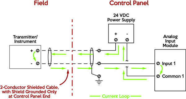
Every 4-20 mA current loop consists of a power source, loop wiring, a sensor/transmitter/receiver at the field end, and a PLC I/O module at the control panel end.
What Are Analog I/O Points and What Do They Measure?
Most analog inputs to a PLC come from transmitters for one of the “big four” sensing parameters:
But there are many other signal options generated by various types of instruments and transmitters, here are just a few:
- Weight
- Electrical voltage, current, or power
- Rotational speed
- Analyzer values such as pH, conductivity, or dissolved oxygen
- Distance
- Potentiometer knob on a control panel
For analog outputs commanded by a PLC, some of the leading targets include:
- Valve position
- Variable frequency drive motor speed
- Setpoints to other instruments and devices
- Digital or analog display on a control panel
Whatever the signal type, it needs to be wired from the field device to the PLC I/O module.
Analog Signal Options
Analog signals for industrial automation operate at low voltages, generally under 24 VDC. Many ranges may be allowable for various PLC I/O modules, but here are the most common:
- Current: 4-20 mA, 0-20 mA, ±20 mA
- Voltage: 0-5 V, 0-10 V, ±5 V, ±10 V
- Millivolt or resistance: thermocouple (TC), resistance temperature detector (RTD)
Bi-directional signals (those with the “±” symbol) are useful with reversing devices (like a motor speed ranging from 100% reverse to 100% forward), or dual-function systems like a heating/cooling package.
Voltage signals are convenient to use with potentiometers, but as we will see this signal type suffers some downsides such as voltage drop over distance and more susceptibility to noise. Potentiometers are largely being replaced by graphical human-machine interfaces. Sensing elements and I/O modules for TCs and RTDs are specialized for direct connection, but many times designers will use field-located transmitters to convert these signals into 4-20 mA to obtain the benefits of this signal type.
Benefits of 4-20 mA Analog I/O Signals
Many industries use 4-20 mA signals because of the following benefits:
- Simple to design, connect, configure, and troubleshoot
- Can travel long distances, typically hundreds or even thousands of feet
- Relatively immune to electrical noise
- The “live zero” at 4 mA makes it easy to detect many failure types
Since these signals drive to a specific current regardless of the resistance in the circuit, they can travel long distances with good resistance to noise.
The final point regarding a “live zero” deserves more explanation. For 4-20 mA loops, 4 mA=0% signal and 20 mA=100% signal. This means there should always be at least 4 mA traveling through the loop. A portion of this 4 mA can be consumed by the field device to power its electronics, so no other separate power is needed. While 0-20 mA is possible, this would mean that 0 mA=0% and therefore the control system couldn’t differentiate between a failed signal or a true 0% signal.
Also, if a loop wire is cut or disconnected, or if a field device totally fails, the current will drop to 0 mA and the connected PLC can detect this as a “open loop” failure. Furthermore, some intelligent devices can be configured to send a high current (perhaps 21.5 mA) upon certain failures, which could also be detected by the PLC.
Loop Power Source, Sinking, and Sourcing
Each 4-20 mA loop must be powered, typically by 24 VDC. Sometimes I/O modules can initiate this power, other times a separate power supply is needed. A “sourcing” configuration occurs when the PLC or the panel it resides in generates the power to the field; a “sinking” configuration occurs when the field device supplies the loop power.
Many modern systems use one field device connected to one PLC I/O point. However, it is possible to wire many indicators or output devices in series within one loop. If this is done, users need to make sure the total impedance in the loop does not exceed allowable values.
Wiring 4-20 mA to Avoid Electrical Noise and Ground Loops
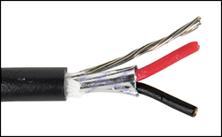
Basic 4-20 mA loops are relatively resistant to electrical noise because they usually have shielded cables and any noise affects both conductors equally. However, best practice is to ground the cable shield at only one end, otherwise a stray current could run through the shield and introduce electrical noise via a ground loop. Also, in certain cases, it is preferred to install optical isolators at one or both ends of the loop to protect against noise. A final consideration for loop cables installed outdoors and subject to lightning is installation of surge suppressors at each end.
Using 4-20 mA current loops for transmitting analog signals to and from PLCs is a straightforward and reliable design method. Following the basic considerations outlined above will provide successful implementations.


I am looking for a CT (0/5V) to 4-20 MA signal converter that meets Class I, Groups B,C,D, Div. 2 that can be installed in the motor conduit box or next to it.
Hi Jose,
Thanks for reaching out! We suggest Allied part number 71091911 (https://www.alliedelec.com/product/phoenix-contact/2902028/71091911/). You can configure the input for 0-5 V and the output to 4-20 mA. Click the link above to go directly to the product. Also, in-depth product information, such as product configuration, can be found here: https://www.phoenixcontact.com/online/portal/us?uri=pxc-oc-itemdetail:pid=2902028&library=usen&tab=1. We hope this meets your needs, but if it does not, for any reason, we’d love to help you find one that does! Just email us at techhelp@alliedelec.com with your contact information so we can work with you directly.
Have a great day!